Frank Vahid
Tony Givargis
Roman Lysecky
Abstract— Embedded systems often implement behavior for common application domains, such as the control systems domain or the signal processing domain. An increasingly common domain is pattern recognition, such as determining which kind of fruit is passing on a conveyor belt. Embedded system students and designers typically are not experts in such domains and could benefit from simpler platforms to help them gain insight into the problem of pattern recognition and help them develop such algorithms rapidly. Generic frameworks, such as PID (proportional- integral-derivative) for control, or FIR (finite impulse response) for signal filtering, empower non-expert embedded system designers to quickly build robust systems in those domains. We introduce a generic pattern recognition framework, useful for education as well as for various real systems. The framework divides the task into three phases: feature extraction, classification, and actuation (FCA). We provide template code (in C) that a student or designer can modify for their own specific application. We show that the FCA pattern recognition framework can readily be adapted for various pattern recognition applications, like recognizing box sizes, fruit type, mug type, or detecting vending machine vandalism, requiring only 2-3 hours to create each new application. We report results of a randomized controlled study with 66 students in an intermediate embedded systems class, showing that the framework could be learned in tens of minutes and yielding applications with higher recognition accuracy of 71% for pattern recognition vs. 57% without the framework (p-value=0.03).
Index Terms—Embedded Systems, Pattern Recognition, Teaching framework, Computer Science Education
I. INTRODUCTION
While many embedded system applications are unique, others implement behavior of well-known domains, illustrated in Figure 1.
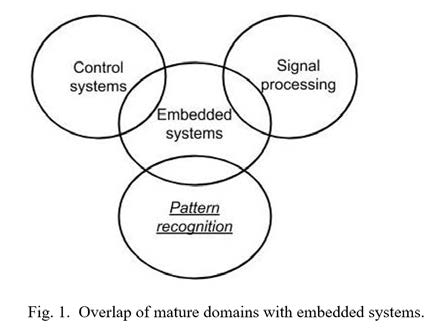
For example, heating an oven to a target temperature, or propelling a small robotic car at a target speed, both represent instances of control systems. A control system [1] strives to control a physical system to match an actual physical feature (temperature, speed) to a target value. A rich discipline of control theory exists, with various mathematical techniques for modeling and controlling physical systems aiming to best match the target (minimizing overshoot, oscillations, and steady-state error) and ensuring stability. However, such theory requires extensive knowledge and training, which many embedded systems students lack early in their careers. Thus, a generic framework for control has been developed, known as PID (proportional-integral- derivative) control [2] to empower non-experts and students to build good quality control systems. The simple concept of PID, plus template code, and techniques for tuning P, I, and D variables in such code, quickly yield systems of sufficient quality for various applications. Without domain experts or knowledge, embedded system students and designers might otherwise develop low-quality control solutions; PID enables such designers to build quality solutions, in the same or even less time as they would otherwise.
Similarly, removing noise from a digital signal, or letting only a certain frequency band pass, both represent instances of digital signal filtering. An FIR (finite impulse response) filter [3] is an easy-to-understand generic framework for filtering in software, allowing non-experts and students to modify variables in template code to implement specific filtering applications.
PID and FIR frameworks each build on existing domain theory to provide simple but powerful methods for embedded system designers and students. Meanwhile, embedded systems are increasingly used to recognize specific patterns. In general, a pattern recognition system takes as input data for an object, and outputs a category for that object. For example, a common such system takes a face photograph as input, and outputs a known person’s name. Most work on pattern recognition systems have a desktop computing model, where input and output are via a file or database. In contrast, a pattern recognizing embedded system, illustrated in Figure 2, gets input from sensors, like weight or color sensors, and generates output by controlling actuators, like changing a directional gate on a conveyor belt, all in real- time. For example, a warehouse may use a pattern recognition system to recognize whether a box on a conveyor belt is one of three sizes, keeping count for inventory purposes. A grocery system may recognize the kind of fruit on a scale (apple, pear, banana) as in Figure 2 and output a total price based on kind and weight.
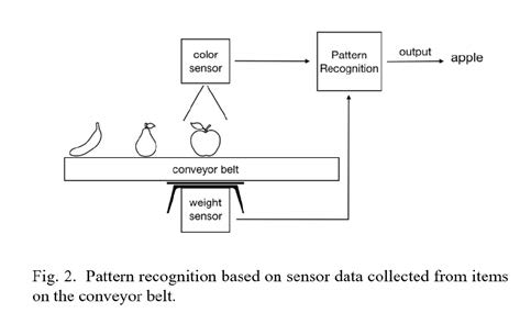
A front-door camera system may detect whether a person is a known person from a database and generate a different doorbell ring for known persons. A wrist-worn device may recognize that an elderly person has fallen and alert caregivers [4]. An embedded camera may be used to detect a red peach [5] on a tree for harvesting. A package express center may use an embedded magnetic matrix and outside sensors to monitor conveyor belt parameters such as tension, load, and position of objects [6]. A system may detect the surface defects on fruits to separate bad fruit from good fruit [7]. A system may be used for detecting the size and grading a fruit to determine its quality [8] for pricing purposes. Governmental organizations may predict floods using pressure and ultrasound flow sensors attached to embedded computer nodes to reduce damages caused by flooding [9]. A traffic system may choose the proper light at intersections to tackle the traffic congestion problem using controllers in traffic lights and sensors on the road [10]. As can be seen, pattern recognition is becoming another common application domain in embedded systems.
Like control systems and signal filtering, pattern recognition is an established domain with extensive theory and techniques. However, many (if not most) embedded systems students and designers do not have that domain knowledge. The pattern recognition domain has dozens of techniques that can overwhelm a student or an embedded system designer who tries to quickly learn about the domain to improve their embedded application. Without access to domain experts, designers may build low-quality pattern recognition systems.
This paper introduces the FCA (feature extraction, classification, actuation) framework for pattern recognition in embedded systems, describes the template code, and summarizes results of using the FCA framework in a classroom setting.
II. FCA FRAMEWORK
Years of engaging with commercial embedded systems applications through various consulting and other arrangements has led to our observation that many embedded applications handle pattern recognition poorly. Some other researchers similarly state the issue [26], with some pointing to issues like limited resources making the pattern recognition problem harder [24], and to the lack of good embedded systems curriculum [25]. In some cases, the developers are not aware of the pattern recognition field or do not realize that their application is performing pattern recognition, and thus the developers do not attempt to draw upon established pattern recognition techniques. Instead, their software may simply use a series of conditions implemented via if-else statements, or a finite state machine, to categorize data coming from sensors. Or, developers may choose a pattern recognition technique but use it poorly. Furthermore, developers may attempt such categorization on raw sensor data. Such software may be making decisions based on too-detailed highly varying input data and may also have actuation distributed throughout the code. The result is a complex piece of software that is hard to update (such as if new sensors are introduced) and that may have low accuracy.
Thus, our first step was to define a modular process specifically for pattern recognition in embedded systems. The process divides pattern recognition into three phases —feature extraction, classification, and actuation, or FCA —shown in Figure 3, whose parts are summarized below.
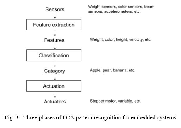
Sensors: The input consists of a combination of various sensors, differing depending on the application. One application may have weight and color sensors. Another application may have color and infrared (IR) break beam sensors. Another may have accelerometers. A designer determines which sensors to use to help with pattern recognition tasks.
Feature extraction: The first phase in pattern recognition is to convert raw sensor data into features that will guide classification. For example, 3-dimensional accelerometer data may be converted into a velocity vector or an acceleration magnitude. Data from several IR sensors may be combined to estimate length, width, and height features, or converted into a volume feature. This phase prevents the common situation of embedded systems designers trying to use raw sensor data directly to make classification decisions. Feature extraction simplifies classification by pre- shaping the data to represent information most useful to classification. For example, in package sorting, box height is more directly useful than data on how many of four vertical IR sensors currently have broken beams (assume multiple IR sensors are stacked at increasing height and a moving box will break a number of the beams depending on its height). The output of feature extraction consists of values for a set of features, such as “height = 3.5 in” and “red = 200” (indicating the amount of red on a scale of 0-255).
Classification: Given values for a set of features of an object, classification determines to which category the object most likely belongs. The output is a single category, such as “apple”, or “small box”.
Actuation: Given a category, actuation takes an appropriate action by setting values of an actuator. If a “small box” is detected in a warehouse system, a stepper motor (a kind of actuator) may be set to guide the box on a conveyor belt to a particular bin. If “apple” is detected in a grocery system, a variable may be set to an appropriate price based on the fruit’s weight.
While seemingly simple, this division into three phases enforces a modularity that developers otherwise might bypass. The division disallows using any raw sensor data in classification, requiring instead that such data be pre-shaped into well-defined features. The division also disallows setting actuators throughout the code; instead, all actuator setting is done after classification is completed. An analog might be made with programming, wherein a function should only read/write its parameters and not global variables – a concept that was not well-understood in the early days of programming, whereas today the importance of modularity with respect to functions is well understood. Using raw sensor data or setting an actuator in the classification code is analogous to reading or writing a global variable in a function, both of which can have unintended side effects and may result in complex hard-to- maintain code. Establishing such modularity is one goal of the FCA framework.
III. CLASSIFICATION
Pattern recognition is a widely studied domain, stemming from the fields of computer science and electrical engineering. The domain goes by various names, including pattern recognition, machine learning, data mining, and knowledge discovery, with papers dating back to the 1960s. As a result, a multitude of techniques exist.
The techniques of most interest to embedded system designers are those known as supervised learning [11], in particular classification. In classification, a set of training objects is provided, with each object labeled as being in a certain category. Then, given a new object, a classification technique, based on the training set, strives to determine in which category the new object most likely belongs, such as: apple, pear, or banana.
For an embedded system designer, trying to determine which classification technique to apply can be overwhelming. For example, the Wikipedia [12][23] entry on supervised learning states that no technique is best and lists many, each technique having extensive literature:
- Support vector machines
- Linear regression
- Logistic regression
- Naive Bayes
- Linear discriminant analysis
- Decision trees
- K-nearest neighbors
- Neural networks
An embedded system designer can be quickly overwhelmed by all the options. Thus, we strove to determine if one technique could serve as a good basis for a generic framework in embedded systems. Our criteria included:
- Simple to learn by embedded system designers
- Good classification accuracy across various common embedded system applications
- Efficiently implemented on resource- constrained embedded platforms
Below, we review K-nearest neighbors, logistic regression, naive Bayes, decision trees, support vector machines, and neural networks along with their advantages and disadvantages based on our criteria.
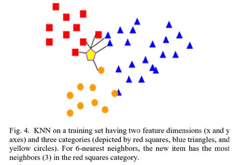
K-nearest neighbor (KNN) [13] is a simple, easily understandable classification algorithm. KNN places known objects in an N- dimensional space, where each dimension is a feature (weight, height, color, etc.). Then, to classify a new object, KNN determines the K closest neighbors in the space; the most common category among those K neighbors wins. Figure 4 illustrates. KNN is powerful and can handle non-linearity and multiclass classification. Moreover, by having a large enough training set, the error rate of KNN would be less than twice the minimum achievable error rate [14]. But, in case of having a large training set, this algorithm can be inefficient in terms of processing time/memory due to the need for storing and searching the training set.
Logistic regression [15] is a linear binary classification algorithm that statistically predicts the odds of an object being in a class based on the features. Logistic regression is fast and efficient in production. However, in this algorithm, objects of different classes should be linearly separable. Therefore, to make the algorithm work well in various embedded systems applications, an additional complex feature representation step is required before classification.
Naive Bayes [16] is a classification algorithm designed based on Bayes’ theorem, and learns the distribution of the input data to predict the probability that an input object belongs to a particular class. Naive Bayes is simple both in concept and implementation and is efficient in production. However, it makes a strong assumption of independence between features of the input data and it suffers in performance when data is sparse in some classes or features, which makes it incompatible with many real- world embedded system applications.
Decision trees [17] are a nonlinear classification technique, which learns simple decision rules from the training set to classify a new input object. Decision trees are easy to interpret and understand. However, decision trees are prone to overfitting (matching particular data too closely, thus being not general) and lack robustness due to high variance in classification accuracy. To increase robustness, one can use an ensemble of decision trees, but that makes the technique more complex for embedded system development.
Support vector machines [18] are a binary classification algorithm, which classifies objects by finding the hyperplane that represents the largest separation between two classes and maximizing their margin. The technique is robust and demonstrated good quality in various embedded systems applications [19, 20, 21]. Moreover, the technique is efficient in production in terms of memory and processing speed. However, the technique’s performance heavily relies on a kernel function, which is not easy to choose especially for non-expert embedded systems developers. Given that support vector machines are mainly binary classifiers and their extension to ternary and higher classification is not very effective, they have limited applicability in the embedded applications.
Neural networks [22] are inspired by the human brain and nervous system. The technique is powerful and has achieved much of the state of the art in the image processing and natural language processing fields. However, the technique is complicated to understand and implement. Moreover, training requires a large amount of data, which often is not available in embedded systems applications.
After some investigation, discussions, and many recommendations from various classification researchers, we chose KNN as the most appropriate general classification technique for embedded systems developers. KNN is highly intuitive: most people can understand the algorithm just by looking at Figure 4. The algorithm is straightforward to code and has small code size and is efficient for moderately-sized training sets as is common in embedded systems. For larger training sets, techniques exist to improve efficiency, such as aggregating objects, caching previous results, etc. The algorithm has demonstrated high accuracy. These features make it a popular choice in general pattern recognition as well but are especially useful in embedded systems due to limitations on code resources (speed, size) and due to ease of understanding and modification by embedded developers.
IV. TEMPLATE CODE
A simple but powerful software productivity improvement techniques is to provide working template code (called “reference code” in many domains) that a developer can modify for his/her particular application. We thus developed template code in C to support the FCA framework. A designer can adjust the code to carry out their own pattern recognition application. Highlights of the code are shown below (the appendix has more complete code); various helper functions and other items have been omitted. A key aspect to notice is the code’s simple organization, enabling a non- expert embedded developer to readily understand, navigate, and modify the code.
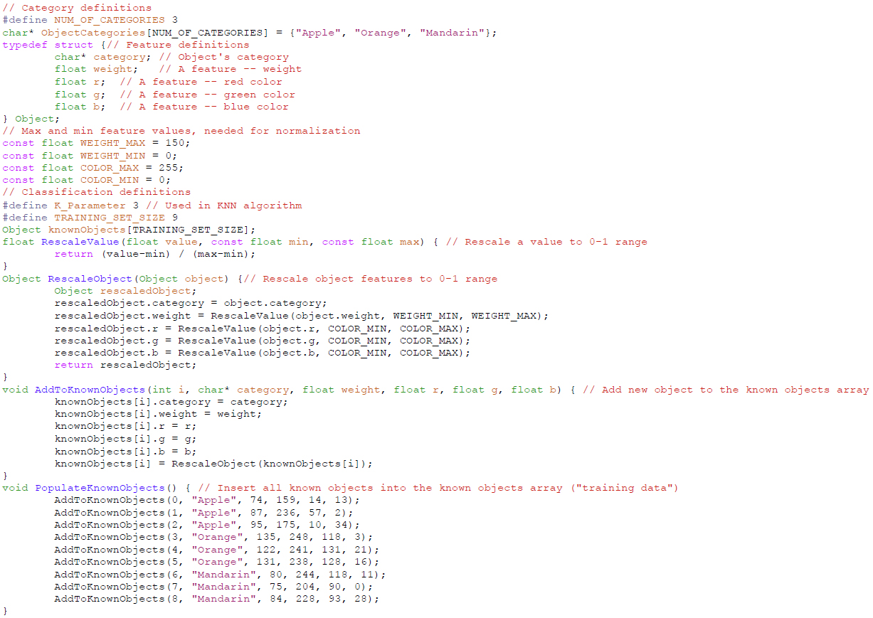
The template code shown in Figure 5 begins by defining a categories array. It then defines a structure for an object (either in the training set, or the new object to be classified), with fields being the object’s category and the various features of the object. It next defines a training set, with functions for populating the set.
Figure 5. Template Code
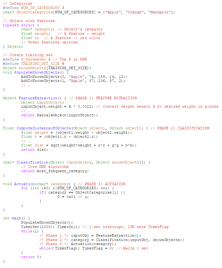
Next, the FeatureExtraction function samples input sensor values and converts those values into desired features. The FeatureExtraction function performs a simple unit conversion. Often, the conversion may involve combining values from multiple sensors, such as converting three x, y, and z accelerometer sensor values into the two features of acceleration direction and acceleration magnitude. FeatureExtraction ends by calling the RescaleObject function to scale all features to values between 0 and 1, so that “distances” make sense in the subsequent KNN algorithm. The RescaleObject function is omitted.
Next, the ComputeDistanceOfObjects function computes the Euclidean distance of any two objects, based on their N (scaled) features in an N-dimensional space. That function is used by the subsequent Classification function, which computes the distance between a new object and every object in the training set, to determine the K nearest training objects, and then returning the most frequent category for those K objects.
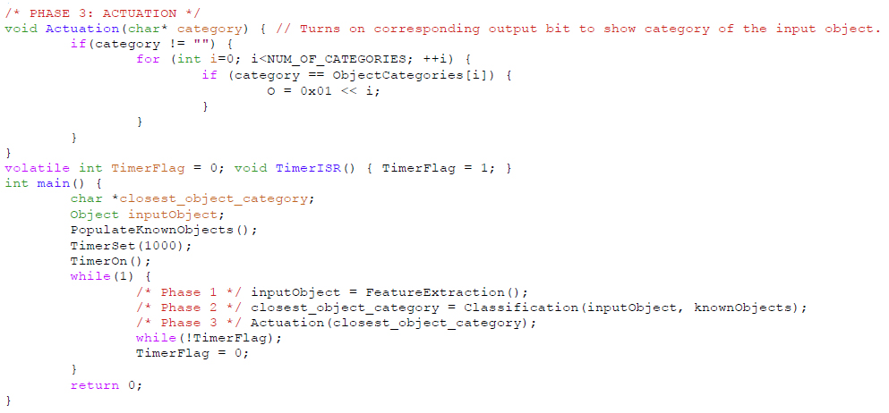
Next, the Actuation function sets outputs (actuators) in response to a given category.
Finally, the main function populates the training set, sets up a sampling rate, and then repeatedly calls FeatureExtraction, Classification, and Actuation at that rate (using a microcontroller’s built-in timer or whatever timing services are provided).
V. ADAPTING THE TEMPLATE FOR VARIOUS APPLICATIONS
We carried out various adaptations of the applications, to gauge the effort required and effectiveness of the resulting system.
The first was an application from a factory warehouse. The system was required to detect which of three sized boxes were on a conveyor belt and direct each box to a different bin for each size. We initially considered a video-based system but decided a simpler approach would be preferable. We used a break beam sensor to detect a box’s presence, and five distance sensors: one to measure height, one to measure width, and two to measure length. The feature extractor included a simple state machine: When the beam was broken, a new box was arriving. When that beam was no longer broken, we considered all the distance sensor values before that moment. With those values, we computed height, width, and length features of the box. For training, we ran the three-sized boxes past the sensors in various orientations and recorded the height, width and length values, yielding 9 training data values. We entered those values into the array of known objects in the template. The entire process of modifying the template code and populating the known objects array with training data required 3 hours. We tested the system with 9 new boxes and obtained accuracy of 100% (9/9 correct classifications).
The second was a grocery store application to detect which types of fruits were passing through on a conveyor belt. The fruits were apples, oranges, lemons, and pears. We used a break beam sensor to detect a fruit’s presence, plus a weight sensor and color sensor. For training, we ran 4 of each fruit through the system to record the fruits’ weights and colors, giving us 16 training values. These values were then entered into the array of known objects in the template. This process took 2.5 hours: one hour to modify the template and the rest spent running and entering the training values. We tested the system with 20 fruits and obtained 19/20 or 95% accuracy – one pear was marked as an apple when its bruised side faced the color sensor.
The third application involved putting a mug on a scale to detect if the cup was an 11 oz mug, a 16 oz mug, or a travel mug. A break beam sensor started the system. We used three distance sensors, two to measure the width of the mug and one to measure the height, and a weight sensor. We trained by sending nine mugs through the system, three of each type. These values were entered into the array of known objects in the template. The process of modifying this code took just under two hours due to us already having the code for the distance sensors and the weight sensor. We tested the system with 6 new mugs and obtained 6/6 or 100% accuracy.
Another application was detecting whether or not a vending machine was being tampered with. In contrast to the above applications that used a break beam sensor to start the pattern recognition process, this application ran the feature extraction part every one second. We used an accelerometer as the only sensor. The sensor provided three values: change in the x axis, change in the y axis, and change in the z axis. Every second, one hundred values were measured with a delay of 10 milliseconds between each measurement. We used a formula to measure the largest change in each axis and these changes were added to the training data, ending with 8 training sets in all, categorized as “normal shaking” or “abnormal shaking”. This application took 4 hours to modify due to the feature extraction portion being different from the other applications. We then gave the device different shakes and obtained 17/20 or 85% accuracy. Here, “accuracy” is less well defined, because humans are the ones defining and judging normal and abnormal shaking, both during training and testing.
It should be noted that, ultimately, the quality of a recognizer’s robustness and accuracy relies on having robust training datasets.
VI. RANDOMIZED CONTROLLED STUDY
To further evaluate the framework’s usability, we conducted an experiment with all 66 students in the Intermediate Embedded and Real-Time Systems class at the (university name withheld for blind review). We randomly divided participants into two groups, A and B.
Both groups started at an “Instructions” web page indicating that they would be participating in an embedded systems coding experiment, and that they were required to work independently and not refer to any outside resources; teaching assistants were present to ensure those rules were met. The instructions indicated that they had 45 minutes, that they were afterwards be given a survey, and that their submissions were anonymized (i.e., no impact on their course grade). Group A had one additional instruction, asking students to complete the tutorial available on the next page, before attempting to code.
Upon clicking “Start experiment”, all students were taken to an “Experiment” page. At the top was a problem description asking to solve a problem of classifying a person to a man, woman, or child category based on the height and weight of the person using training data for 18 people. Beneath the problem statement was an embedded systems simulator where students could write C code to read from microcontroller inputs and write to outputs; students had been using this simulator throughout the quarter already. The simulator showed its standard code for both groups, consisting of required includes at the top, and a main function consisting of a timer initialization followed by an infinite while(1) loop.
The only difference between the groups here was that Group A saw a button at the top labeled “Tutorial”, while that button was not present for Group B. The button for Group A led to a brief discussion on pattern recognition along with FCA template code and an example. Note that the instructions did not tell Group A students that they were required to use the template code.
Upon reaching that experiments page, a timer at the top of the page immediately started counting up from 0 minutes. The teaching assistants ensured all students stopped before reaching 45 minutes.
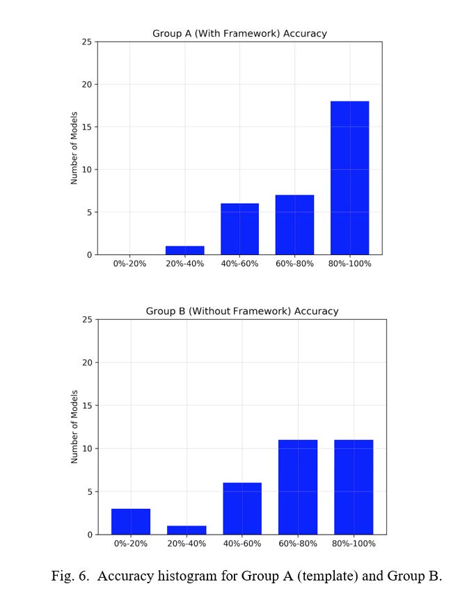
We evaluated the submitted models on one hundred test cases. As we assumed (and hoped), all Group A students chose to use the FCA template code in their solutions. Table 1 shows the average accuracy and average time spent to solve the problem for each group. The comparison verifies that access to the classification resources in group A led to the development of significantly more accurate models (p=0.03 using an independent t-test), and that the provided template was quickly learnable.

Figure 6 provides a detailed view of the accuracies obtained by each group; Group A had many more applications with 80-100% accuracy, and none with 0-20% accuracy that occurred for some in Group B.
Analysis of the submission time information shows that participants in group A spent slightly higher time to solve the problem compared to group B. This is mostly due to group A needing to take extra time to read the tutorial and review and understand the reference code, which is a one-time overhead that would be reduced if the individual used the framework again.
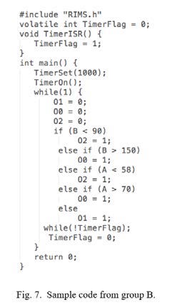
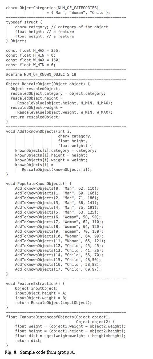
Also, a more detailed study of submitted models shows that similar to the sample model displayed in Figure 7, all participants in group B used a series of branch statements to solve the problem (as we had observed in various commercial applications, mentioned in Section 2). In contrast, all participants in group A copy- pasted and modified the template code, as in Figure 8, even though the default code provided to group A was only a basic main() function with a timer and infinite loop, identical to group B.
Discussion: Some might say that Group A of course would do better because they received a tutorial and template code. However, such better performance was not a forgone conclusion. If FCA was not easy to understand, and if the code template was large or confusing,
Group A students might have chosen to ignore the FCA code and write their own code, as Group B did. Or, Group A students might have tried to use the FCA template code but failed to complete the task or created inferior solutions. Indeed, many of the pattern recognition techniques would have been almost impossible to teach and gain success in such a short period of time. We intended to show that FCA is quickly learnable and effective, and the results seem to support that hypothesis.
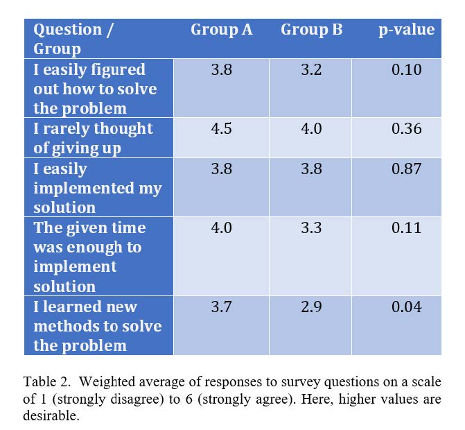
After submitting the code, participants took a survey with seven questions regarding solving the problem and the tool. Each question in the survey had six options representing the level of agreement with the question statement. We converted those options into numbers from 1 to 6, where 1 corresponds to the strongly disagree option, and 6 corresponds to the strongly agree option. Table 2 shows the weighted average responses of each group. The results show a slight improvement across 4 of the 5 questions, though not statistically significant except for the last question. The conclusion here is that the extra work of the FCA tutorial in the short available time did not create any extra stress or confusion.
VII. RANDOMIZED CONTROLLED STUDY
Pattern recognition applications continue to grow in embedded systems. We developed a framework to enable embedded systems students and designers to readily build robust pattern recognition applications, without having pattern recognition domain expertise. The framework divides pattern recognition into three phases: feature extraction, classification, and actuation (FCA). We chose K-nearest neighbors for classification due to simplicity and robustness. We developed template code in C for the FCA framework with great emphasis on simplicity.
We found that we could adapt the template code to four different applications in just a few hours for each, with highly accurate classification. We conducted an experiment showing students could readily understand the code and adapt it for a given application, yielding significantly improved recognition accuracy.
Embedded system students typically are not experts in such domains and could benefit from simpler platforms to help them gain insight into the problem of pattern recognition and help them develop such algorithms rapidly. This work contributes to this educational mission. Furthermore, many embedded systems engineers are non-experts as well. This work enables engineers to build robust pattern recognition systems without being an expert in the pattern recognition field, akin to how PID control and FIR filters enable engineers to build robust control or filtering systems without being experts in those fields.
APPENDIX
This appendix provides a nearly complete listing of the template code, as shown in Figure 9. Much attention was paid to keeping the code as short and simple as possible, to enable rapid understanding by embedded developers.
Figure 9. Nearly complete code listing.
ACKNOWLEDGEMENT
This work was supported in part by the National Science Foundation (NSF grant number 1563652). We thank Shayan Salehian and Bailey Herms, whose masters projects contributed to this work.
REFERENCES
[1] Dorf, R. C. and Bishop, R. H. (2011). Modern control systems. Pearson.
[2] Wescott, T. (2000). PID without a PhD. Embedded Systems Programming, 13(11), 1-7.
[3] Wagner, B. and Barr, M. (2002). Introduction to digital filters. Embedded Systems Programming, 47.
[4] Bourke, A. K., O’brien, J. V., and Lyons, G. M. (2007). Evaluation of a threshold-based tri-axial accelerometer fall detection algorithm. Gait & posture, 26(2), 194-199.
[5] Teixidó, M., Font, D., Pallejà, T., Tresanchez, M., Nogués, M., and Palacín, J. (2012). An embedded real-time red peach detection system based on an OV7670 camera, arm Cortex- M4 processor and 3D look-up tables. Sensors, 12(10), 14129-14143.
[6] Pang, Y. and Lodewijks, G. (2006, June). A novel embedded conductive detection system for intelligent conveyor belt monitoring. In International Conference on Service Operations and Logistics, and Informatics, pp. 803- 808). IEEE.
[7] Davenel, A., Guizard, C. H., Labarre, T., and Sevila, F. (1988). Automatic detection of surface defects on fruit by using a vision system. Journal of Agricultural Engineering Research, 41(1), 1-9.
[8] Dang, H., Song, J., and Guo, Q. (2010, August). A fruit size detecting and grading system based on image processing. In Intelligent Human-Machine Systems and Cybernetics (IHMSC), 2010 2nd International Conference on (Vol. 2, pp. 83-86). IEEE.
[9] Hughes, D., Greenwood, P., Coulson, G., and Blair, G. (2006). Gridstix: Supporting flood prediction using embedded hardware and next generation grid middleware. In World of Wireless, Mobile and Multimedia Networks, 2006. WoWMoM 2006. International Symposium on a (pp. 6-pp). IEEE.
[10] Thakare, V. S., Jadhav, S. R., Sayyed, S. G., and Pawar, P. V. (2013). Design of smart traffic light controller using embedded system. IOSR Journal of Computer Engineering (IOSR-JCE), 10(1), 30-33.
[11] Russell, S. J., Norvig, P., Canny, J. F., Malik, J. M., & Edwards, D. D. (2003). Artificial intelligence: a modern approach (Vol. 2, No. 9). Upper Saddle River: Prentice hall.
[12] Supervised learning. (2018, February 28). Retrieved March 08, 2018, from https://en.wikipedia.org/wiki/Supervised_learning
[13] Cover, T. and Hart, P. (1967). Nearest neighbor pattern classification. IEEE transactions on information theory, 13(1), 21-27.
[14] Elkan, C. (2011, January). Nearest neighbor classification. elkan@cs.ucsd.edu.
[15] Hosmer Jr, D. W., Lemeshow, S., and Sturdivant, R. X. (2013). Applied logistic regression (Vol. 398). John Wiley & Sons.
[16] Theodoridis, S. and Koutroumbas, K. (2008). Pattern Recognition. Elsevier Science.
[17] Duda, R. O., Hart, P. E., and Stork, D. G. (2012). Pattern classification. John Wiley & Sons.
[18] Cristianini, N. and Shawe-Taylor, J. (2000). An introduction to support vector machines and other kernel- based learning methods. Cambridge university press.
[19] Shi, G., Chan, C. S., Li, W. J., Leung, K. S., Zou, Y., and Jin, Y. (2009). Mobile human airbag system for fall protection using MEMS sensors and embedded SVM classifier. IEEE Sensors Journal, 9(5).
[20] Meng, H., Pears, N., & Bailey, C. (2007, June). A human action recognition system for embedded computer vision application. In Computer Vision and Pattern Recognition, 2007. CVPR’07. IEEE Conference on (pp. 1-6). IEEE.
[21] He, Z. Y. & Jin, L. W. (2008, July). Activity recognition from acceleration data using AR model representation and SVM. In Machine Learning and Cybernetics, 2008 International Conference on (Vol. 4, pp. 2245-2250). IEEE.
[22] Hagan, M. T., Demuth, H. B., and Beale, M. H. (1996). Neural network design (Vol. 20). Boston: Pws Pub.
[23] Wolpert, D. H., Macready, W. G., No Free Lunch Theorems for Search, Technical Report SFI-TR-95-02-010, 1995.
[24] Ring, Matthias, et al. “Software-based performance and complexity analysis for the design of embedded classification systems.” Proceedings of the 21st International Conference on Pattern Recognition (ICPR2012). IEEE, 2012.
[25] Ricks, K., D. Jackson, and W. Stapleton. Incorporating embedded programming skills into an ECE curriculum. ACM SIGBED Review, January 2007.
[26] Perez-Cortes, JC, JL Guardiola, and AJ Perez-Jimenez. Pattern Recognition with Embedded Systems Technology: A Survey. 20th Int. Workshop on Database and Expert Systems Application, 2009.
